GPIO Experiment 1: From Linux Command to Electrical Signal
Controlling a Raspberry Pi GPIO pin and verifying its electrical output.
In our previous experiments, we prepared a Raspberry Pi 4 running Linux and examined its kernel preemption configuration.
Now we’ll move beyond inspecting software and interact directly with the physical hardware.
Can a command entered into a Linux terminal control the voltage on a Raspberry Pi connector?
In this experiment, we’ll configure a General-Purpose Input/Output (GPIO) pin, switch its output between LOW and HIGH, and verify the resulting voltage using a digital multimeter.
Tested configuration: Raspberry Pi 4 Model B Rev 1.5, Raspberry Pi OS Lite 64-bit, Linux kernel 6.18.50+rpt-rpi-v8. GPIO measurements obtained using a HABOTEST HT118D digital multimeter.
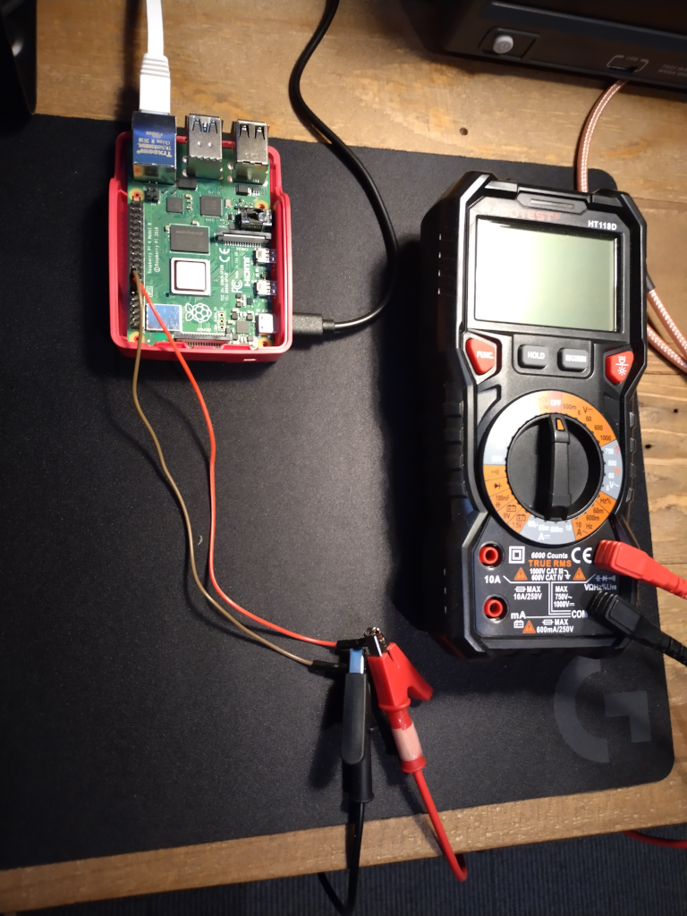
Raspberry Pi 4 GPIO18 voltage measurement setup.
1. Understanding Raspberry Pi GPIO
The Raspberry Pi 4 provides a 40-pin header that exposes digital input/output signals, power connections, ground connections and several specialised hardware interfaces.
A GPIO pin can be configured by software to act as a digital input or output.
When configured as an output, the pin can drive two logical states:
- LOW — approximately 0 V
- HIGH — approximately 3.3 V
These are electrical voltage levels, not merely abstract software values.
For our experiment, we’ll use BCM GPIO18, which corresponds to physical pin 12 on the Raspberry Pi’s 40-pin header.
It is important to distinguish these numbering systems. BCM numbering identifies signals within the Broadcom GPIO controller, while physical numbering identifies positions on the connector.
2. Hardware setup
Our laboratory consists of:
- Raspberry Pi 4 Model B
- Digital multimeter (HABOTEST HT118D)
- Two Dupont jumper wires
- Linux workstation with SSH access
We connect the multimeter as follows:
| Connection | Raspberry Pi header |
|---|---|
| Multimeter positive (red) | Physical pin 12 — BCM GPIO18 |
| Multimeter negative (black) | Physical pin 14 — GND |
The multimeter is configured for DC voltage measurement, using its 6 V range.
The black lead is connected to the COM socket and the red lead to the VΩHz socket.
Important: Power off the Raspberry Pi before attaching the jumper wires. GPIO signals operate at 3.3 V and must not be connected directly to a 5 V supply. Avoid accidental short circuits between adjacent header pins.
No external power supply, LED or resistor is required. The multimeter presents a high-impedance measurement load.
3. Connect to the Raspberry Pi
From our Debian Linux workstation, establish an SSH session:
ssh pi@pi4.local
We use the Raspberry Pi pinctrl utility to inspect and control GPIO configuration.
Verify that it is installed:
which pinctrl
Our system reported:
/usr/bin/pinctrl
The utility provides direct access to pin configuration and state, making it suitable for a simple hardware experiment.
4. Inspect the initial GPIO state
Before changing anything, inspect GPIO18:
pinctrl get 18
Our Raspberry Pi reported:
18: ip pd | lo
The important fields are:
| Field | Meaning |
|---|---|
18 | BCM GPIO number |
ip | Configured as input |
pd | Internal pull-down enabled |
lo | Logic level currently LOW |
This establishes our starting point: GPIO18 is configured as an input with an internal pull-down.
With the multimeter connected between GPIO18 and ground, the voltage was approximately zero.
5. Drive GPIO18 HIGH
Now configure GPIO18 as an output and drive it HIGH:
pinctrl set 18 op dh
The arguments mean:
18— select BCM GPIO18op— configure the pin as an outputdh— drive the output HIGH
The multimeter immediately indicated:
3.301 V
This is the expected voltage for a 3.3 V GPIO output.
A command executed through an SSH terminal has changed the electrical potential of a physical connector on the Raspberry Pi.
6. Drive GPIO18 LOW
Next, drive the same output LOW:
pinctrl set 18 op dl
The multimeter now indicated:
0.000 V
The GPIO signal has returned to ground potential.
We can repeat the two commands to switch the output between HIGH and LOW.
Our measured results were:
| GPIO state | Measured voltage |
|---|---|
| HIGH | 3.301 V |
| LOW | 0.000 V |
The measurements confirm that the software commands produce the expected electrical output levels.
7. Restore the original configuration
After completing the experiment, return GPIO18 to its original input configuration:
pinctrl set 18 ip pd
Verify the result:
pinctrl get 18
Expected output:
18: ip pd | lo
The pin is once again configured as an input with its internal pull-down enabled.
Restoring the initial configuration is good laboratory practice, particularly when the same hardware will be used for subsequent experiments.
8. What have we established?
We have demonstrated a complete path from software to hardware:
- A command is entered into a remote Linux terminal.
- The
pinctrlutility configures the Raspberry Pi GPIO controller. - The GPIO controller drives a physical output pin.
- The multimeter measures the resulting voltage.
The measured HIGH and LOW voltages closely match the expected 3.3 V and 0 V levels.
This establishes that we can control and observe a physical electrical signal using ordinary Linux commands.
However, the experiment tells us nothing about the timing precision of that control.
A digital multimeter can confirm static voltage levels, but it cannot reveal short-term timing variations.
What happens if we repeatedly switch GPIO18 HIGH and LOW at a specified frequency?
Will the resulting waveform have precisely uniform timing, or will Linux scheduling and other system activity introduce variation?
In our next experiment, we’ll use an oscilloscope to investigate the timing behaviour of a GPIO signal.
This will provide the first step toward measuring Linux scheduling jitter and exploring the practical significance of PREEMPT_RT.